| Programs used: Microchip IDE, Agilent Capture | Skills needed: Assembly, Analog & Digital, USART, SSI |
Project Background
|
Wedding photographers were students of light. It took knowledge and experience to be able to set the lighting for a properly exposed picture.
Most photographers would shoot with the flash in Manual mode. When a flash is operating in Manual mode it puts out a fixed amount of light.
While this produced the most consist results, it required the photographer to know how much light was reaching the subject at a fixed distance.
It was a delicate balance of the naturally occurring light, the flash power setting, and the camera aperture setting. It required that the photographer take a meter reading to measure the ambient light, set his camera to the appreciate setting for the picture. Then the photographer had to know the setting for the flash to produce the desired amount of light at the current distance to the subject. Camera companies had simplified this procedure by creating a TTL (through the lens) metering system. With the TTL system, the camera would meter the ambient light and set the camera for the photographer. The camera would then send all the information, through the hot shoe, to a flash. This worked well, but there was a drawback. The camera had to be used with a dedicated flash. With the older manual system, a photographer could use any flash with any camera. Now to get the simplicity of TTL metering, the photographer had to give up flexibility in equipment. Our flash had been around for approximately five years, and was used mainly in manual mode. Now it was time for a big leap. The Qflash is a powerful and versatile flash, but it was never intended to be mounted in the hot shoe of a camera like the smaller dedicated flashes that use TTL. It was time to make a smaller version that could be used in the hot shoe of a camera. But now we faced a problem. Once a flash (or any device) mounts into the hot shoe, it needs to be able to integrate itself into the camera. There is a constant stream of data between the camera and the flash that is in the hot shoe. What scheme are they using to communicate? USART? SSP? SCI? Even if we determined the scheme there is still the task of decoding the data. Of course none of the camera manufacturers would provide any information. They had their own product to sell and were not interested in lending a hand. It was my task to determine the communication scheme, decode the data, and design a circuit that would communicate with the camera. |
How It Was Done
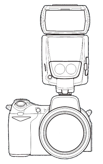 |
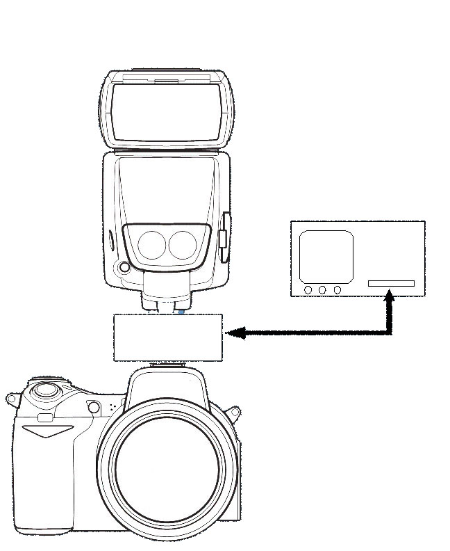 |
The first step was developing a circuit that would allow me to tap into the signals passing between the camera and a standard TTL
flash. With this circuit I could view the data on a scope, but I could also determine which direction the signals were traveling in.
Once I had this circuit, I could begin the work required to decode the data. The circuit also provided a template for the final interface circuit. |
The Pay Off
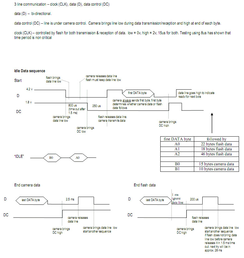
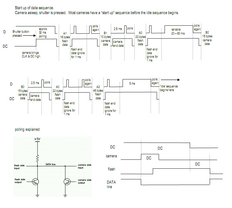
| This was a huge break through for us. The data could be viewed, stored, and compared. It was a slow and methodical process but we now had a way for determining all the data sent from and to the camera. Below are some of my notes that lead to the development of several major products. | |
 |
 |